Important things to know when installing a tank tee on your new pressure tank!
 This article provides information to help you avoid making common mistakes when installing a tank tee or new components which are directly attached to the tank tee. It all seems quite simple at a glance, however without proper understanding of how all the components work together, it is not uncommon for the installation to be completed using all new components, and the system simply will not work. When the system fails to operate properly, the automatic conclusion is that the pressure switch is defective, when the actual issue is that the pressure setting relationships between the switch cut-in, and the tanks pre-charge pressure will not trigger the cut-in (pump start). For a deeper dive into this visit the links below:
https://support.boshart.com/trouble-shooting-my-water-flow-stops-before-my-pump-starts
https://support.boshart.com/how-do-i-adjust-a-pressure-switch
Getting Started
 First off it is crucial that a suitable tank tee is selected! The link below takes you to an article which has detailed information on what you need to know about your pressure tank before you can select a tank tee:
The article covers:
- Determining the minimum Center End Length (CEL)
- Union tank tees vs. solid (non-union) tank tees
- The pros and cons of the various materials available
Selecting the right tank tee is the starting point for ordering a tank tee fittings package or ordering the components separately. Let’s look at things you need to know to avoid potential problems and be aware of before selecting the components.
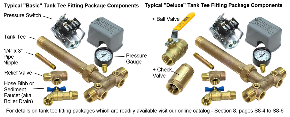
The link below goes over the components typically included in a basic as well as some “deluxe” tank fitting packages.
https://support.boshart.com/selecting-a-tank-fitting-package
Pressure Switch Cut-IN (Pump Start) Setting vs. Tank Pre-Charge Setting
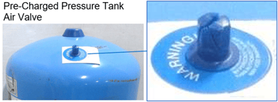 The pressure switch cut-in setting to the tanks pre-charge pressure (PSI) should be for 4-5 PSI difference, most tank manufacturers state 2 PSI. However, this small difference is often not enough to compensate for ambient temperature variations and slight differences in the accuracy of the pressure gauge and gauges used to test the tanks pre-charge PSI.
Pressure Switch Selection
Type - There are numerous pressure switch options, three of the most common are listed below in order of popularity, this does not mean one is better than the other.
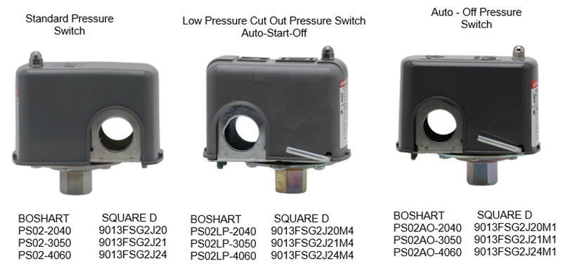
Option #1 - The “standard” most common used pressure switch is the standard action ON-OFF (Cut-In – Cut-Out) such as the Square D 9013FSG2 or Boshart PS-02. They tend to be less prone to cause issues than the low-pressure cut-out switches, however they do not provide any protection for your pump in the event the well runs dry.
Option #2 – If you need to have low water protection you will need to install a switch with a low pressure cut out Square D 9013FSG2 Form M4 or Boshart PS-02LP, which will shut down the pump if a low-pressure situation occurs, such as the well running dry or a catastrophic pipe break. The switch will shut down if the pressure drops 10 PSI below the switch cut-in setting. For example, if you install a 30-50 psi pressure switch, if the pump runs dry and the pressure drops to 20 PSI or less the switch will trip to a maintained off position, shutting the pump off. The pump will not restart until the problem has been corrected and the switch lever is manually held in the start position until the pressure builds up to or above the cut-in (Pump Start) setting of 30 PSI. When the pressure is back up the lever can be released, and it will then be in the automatic run mode.
https://support.boshart.com/what-is-a-pressure-switch-with-low-pressure-cut-off-feature
Option #3 – A less common option is an Auto-Off switch that allows the system to be turned off by positioning the lever on the pressure switch Square D 9013FSG2 Form M1 or Boshart PS-02AO to the OFF position. The switch is in a “maintained” off position and the system is locked out until someone manually moves the lever into the AUTO mode position. These are often used in cottage country where the operator may want to shut the pressure system down when the property is vacant for periods of time.
https://support.boshart.com/what-are-the-applications-for-an-auto-off-pressure-switch
Electrical Rating – - The vast majority of submersible pumps used in residential water systems will be 1.5 HP or less. Most standard duty pressure switches such as the Boshart PS-02, Square D 9013FSG2 or Furnas - Hubbell 69ES Series are rated for 1.5 HP 115 / 120-volt single phase or 2 HP 230 / 240-volt single phase power. Always verify the electrical ratings with the switch manufacturer.
https://images.boshart.com/boshartimages/2022/04/PS02-SERIES-SMALL-WATER-PUMP-SWITCHES.pdf
https://images.boshart.com/boshartimages/2022/06/69ES-literature-2006.pdf
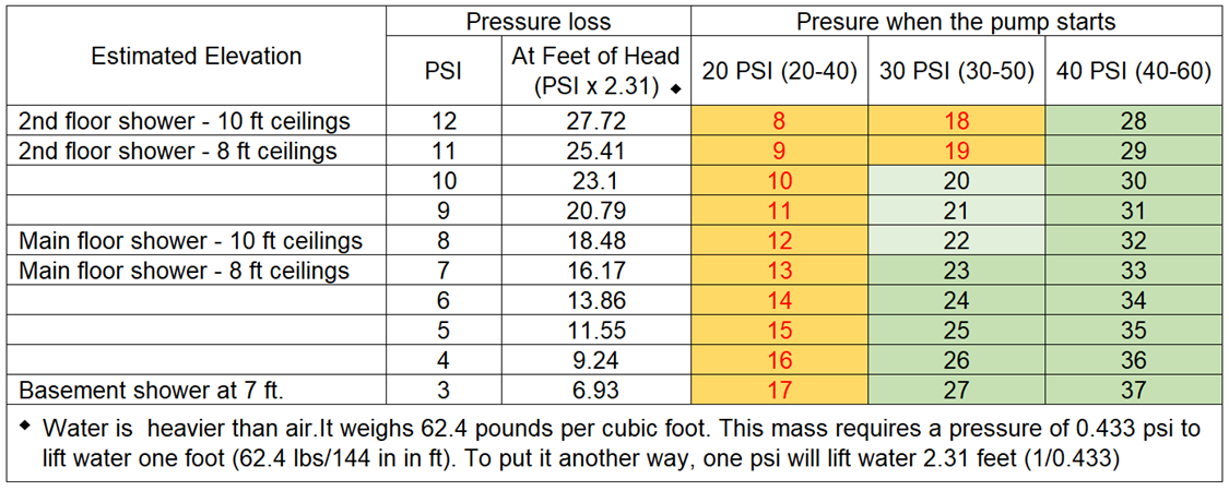
Pressure Settings CUT-IN & CUT-OUT - The pressure switches are typically available in three common pressure settings, 20/40, 30/50 and 40/60. The 20-40 pressure switch setting is the least common, 30/50 and 40/60 are the two common settings with the 40/60 gaining in popularity as homeowners like having higher water pressure.
One of the key factors in selecting a pressure switch setting is the elevation from the water system pressure tank outlet to the outlet of the highest fixture, which is typically the shower head on the top floor. For example, if the tank is in the basement of a two-story home with 8-foot ceilings we can estimate that the shower head of a basement shower is at 7 feet, the main floor shower head at 16 ft and the second-floor shower head is at 25 feet above the tanks’ discharge. However, if you have 10 foot ceilings, you will be more in the range of a basement shower at 7 feet, the main floor shower head at 18 ft, and the second floor shower head is at 27 feet above the tanks discharge. For every 2.31 feet of elevation (feet of water) it requires 1 PSI to lift the water.
Generally, homeowners do not like the water pressure to drop below the 20 PSI range before the pump starts and pressure starts to build up to the pumps cut-out setting.
The good news is, if you purchase the wrong pressure setting there is no need to worry. All the switches can be adjusted to change the cut-in and cut -out settings in the field. The link below has detailed information on how to make the adjustments.
https://support.boshart.com/how-do-i-adjust-a-pressure-switch
Pressure Gauge Selection
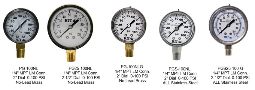
Construction – If you have selected a brass tank tee, it is suggested to select a brass pressure gauge with a brass connection and a stainless steel connection with a stainless steel gauge. ¼” MPT lower mount (LM) connection gauges are used with tank tees.
Dial Size – Either 2” or 2-1/2” dial gauges will work on the tank tees. The benefit of a larger dial gauge is the ease of readability, but they will be slightly higher in cost. It will have no effect on the systems operation.
Dry vs. Liquid Filled – Again it will have no effect on the systems operation, the benefits of a liquid filled gauge is increased life expectancy since all the fine gears and linkages inside the gauge are always lubricated and vibrations are dampened, lowering the rate of wear on all the components. The dampening of vibrations also stops the needle from fluttering for ease of readability. You can never go wrong by selecting a liquid filled gauge, however one must vent the gauge by snipping the tip off the sealing plug after installation, so that the internal gauge pressure is always equalized with the atmospheric pressure, otherwise a liquid filled gauge will not read accurately.
https://support.boshart.com/what-are-the-advantages-of-installing-a-liquid-filled-gauge
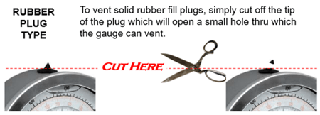
https://support.boshart.com/how-do-i-vent-a-liquid-filled-gauge
Accuracy – Typically the gauges used in pressure systems are the standard 3-2-3 accuracy, which is sufficient, however a gauge with a higher degree of accuracy always helps when setting a pressure switch more accurately. This is beneficial when setting the pre-charge of your pressure tank 4-5 PSI below the switch cut-in setting. You may want to select a gauge that has either a 1.5% or 1% full scale accuracy.
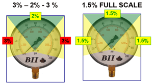
Measurement Accuracy (% of Full Scale): In cases where the accuracy differs between middle span and the first and last sections of the scale, the largest % error is reported on the first and last sections of the scale.
Range - The pressure gauge selected should have a full-scale pressure such that the operating pressure occurs in the middle half (25% to 75%) of the scale (12 o'clock position is best). The full-scale pressure of the gauge selected should be approximately two times the intended operating pressure. This will give the operator a visual indication of normal, ideal operating conditions. This means you can tell the system is working properly at a quick glance, with the needle pointing upwards between 10 and 2 O-clock the system is operating the way it should be. If, however, the "visual" of the pointer is way below 10 or way above the 2 o'clock position, then you may have a situation that needs attention.

https://support.boshart.com/pressure-gauge-range-selection
Relief Valve
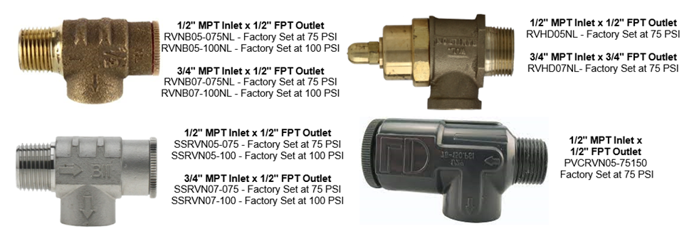
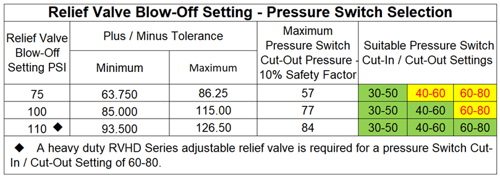
Blow-Off Setting – The opening pressure setting is critical, economy relief valves RVNB and SSRVN Series are factory set at either 75 PSI or 100 PSI. However, one must take into account that they have a plus / minus tolerance of 15% which must be considered when selecting the pressure switch setting 20-40, 30-50, 40-60 or 60-80, which may also have a small margin of error. If the blow off pressure is too close to the maximum system pressure, the risk of a nuisance blow off increases. In the event you are running higher pressure settings such as 60-80 for example you will have to purchase a Heavy Duty “Deluxe” RVHD Series relief valve and adjust the blow off to around 110 PSI, see the chart below.
https://support.boshart.com/how-do-i-adjust-a-relief-valve
Connection size – You must select the proper relief valve size. 1” tank tees typically have ½” FPT, whereas 1-1/4” tank tees have 3/4” FPT accessory ports for the relief valve and sediment faucet (boiler drain).
Tank Location – Relief valves have threaded outlets for a reason! They MUST be plumbed to a suitable drain which can drain the volume of water sufficiently. They are designed to open if there is a spike in the system pressure for any reason. One reason can be pressure switch failure, which results in the switches contacts not opening to shut off the submersible pump when the Cut-Out setting is reached. If the contacts have arced and welded together the pump will stay on and build pressure to whatever the pump is capable of producing. Water damage caused by failure to properly install the relief valve with proper draining capacity in the event of a blow off is the sole responsibility of the installer.
Drain Valve
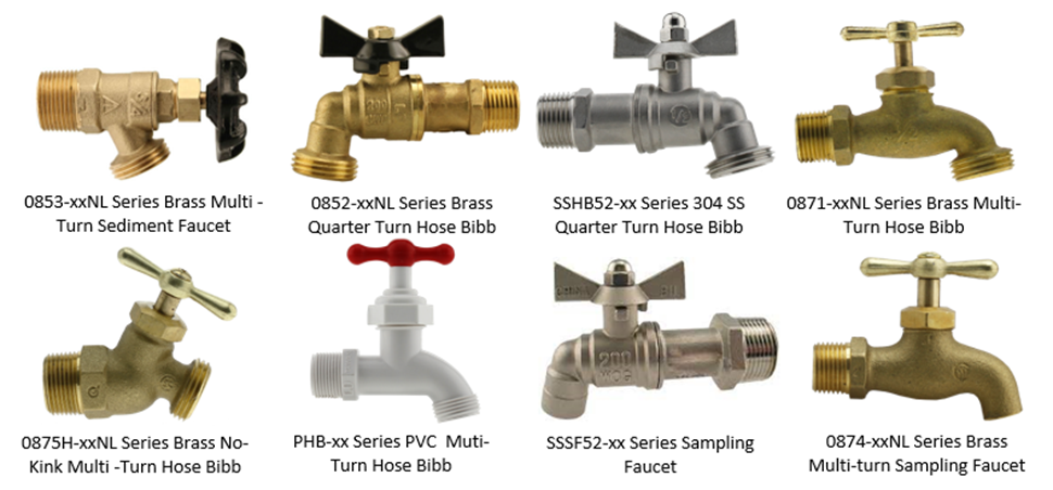
Check your Well construction and Plumbing Codes – In the vast majority of areas the drain valve is a standard Sediment Faucet (aka Boiler Drain) which has a garden hose thread on the outlet for attaching a hose when the tank needs to be changed or drained. However, in some areas the local plumbing code requires the installation of a “Sampling Faucet.” A sampling faucet does the same function, with the difference being that there is no GHT thread on the outlet or spout to connect a hose. The reason is that they do not want garden hoses attached to the water system for water sampling reasons.
Additional Good Advice!
Purchase a Union Tank Tee - Selecting a “Union Tank Tee” is the best option hands down!
Install Unions in the line connections - Install additional unions in both line connections for ease of replacement in the future.
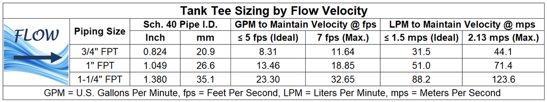
Do not reduce tank tee size - Tank tee size should be equal to the tank connection size (1 inch vs 1-1/4”). One should not reduce the tee size as this will increase the flow velocity through the piping. The piping from the submersible pump and the tee size should be sized to maintain the flow velocity at 5 fps (Feet Per Second) or 1.5 mps (Meters Per Second). You will need to know the submersible pumps capacity.
The link below to Flomatic’s online Velocity Calculator is a handy tool when selecting piping size for your project.
https://www.flomatic.com/downloads/water-velocity-calculator/
Flow velocity is very important to take into consideration when selecting piping components. Valves and fittings are more expensive, however keeping the water velocity low is important to limit pressure losses due to friction, water hammer, and pipe movement caused by water momentum changes inside the pipe. It is recommended to size piping to maintain a water velocity of 5 ft/second (1.524 LPM). Five feet per second is a threshold that is widely accepted by engineers and designers because beyond this velocity, the friction losses, danger of water hammer, and pipe movement due to water momentum changes are deemed to be too high.
Plumb using the external line connections - The tank tees are manufactured with dual external MPT threads and internal FPT threads on the line connections. This limits the possible wall thickness. The wall thickness is limited more on 1” tank tees which have 1” MPT external threads and ¾” FPT internal thread. The issue is not as pronounced on the 1-1/4” tank tees which have 1-1/4” have 1-1/4” MPT external threads and a 1” FPT internal thread. Connecting lines to either the internal or external connections is suitable, however when using the internal connections to use smaller size, less expensive fittings, or valves for cost savings, one must use proper installation techniques, and take great care to not over tighten the fittings in the internal connections.
The use of the external threads also eliminates issues related to flow restriction or friction loss. This is generally more important on the pump line connection.
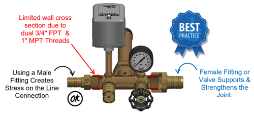
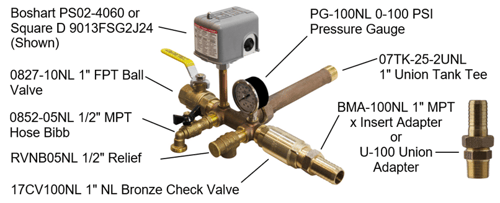
The photo below shows an ideal installation in which the tank tee line connection to water line from the well / submersible pump is furnished with a check valve threaded onto the external thread and converted to a barbed fitting for polypropylene (PE) water line. The selection of a U-100 bronze union adapter is a great option, as it makes the transition from thread to barbed insert and also provides a union connection which makes replacement of the check valve a quick & simple task. The line connection to the household plumbing is furnished with a shut off ball valve threaded onto the external thread. The installation of a union close to the ball valve in the discharge line is also advised for ease of replacement of any of the components in the future.
Avoid joining dissimilar metals - Whenever possible select and connect fittings of the same material to eliminate the risk of galvanic corrosion. See the link below for some solutions for installing a barrier between dissimilar metals.
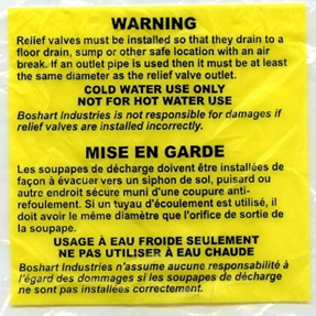 Plumb relief valve outlet to a suitable drain! - Run the drainpipe to an open floor drain. Never obstruct the drain line in any way. A relief valve functions, in an emergency, by discharging water. Therefore, it is essential that a discharge line be piped from the valve in order to carry the overflow to a safe place of disposal. The drainpipe must be the same size as the valve outlet and must pitch downward from the valve.
In Conclusion
We trust that this information has been helpful, please let us know if you have questions that have not been addressed.
 It is important that you always refer to and follow the manufacturer's instructions, and all the applicable plumbing, well construction, and building codes. All plumbing must conform to building codes and national plumbing codes which generally apply to the entire country. In addition, you must also follow any additional local codes, which could be more stringent. You can request information about local plumbing codes from your local building department.