The following is a step by step procedure for adjusting your pressure switch. All pressure switches have two operating points known as the cut-in (Reset Point) and cut-out (Trip Point) settings. The cut-in point is for the falling pressure and the cut-out point is for the rising pressure. Every switch also includes a differential, or a range based on the cut-in and cut-out points. Both the cut-in and cut-out on most switches can be adjusted if certain applications require that. For example: if the cut-in is 40 PSI and the cut-out is 60 PSI the differential is 20 PSI.
1. Monitor the pressure gauge during operation to determine the points where the pressure switch turns on and off.
2. Determine whether to adjust the cut-in, cut-out, or both.
3. If using a tank with an air bladder, determine what air pressure is required in the bladder.
NOTE: Follow the manufacturer's instructions for setting the air pressure to the required level for the newly adjusted pressure switch settings. When instructions are not available, always set the air pressure in the bladder to 2 psi below the new desired cut-in pressure.
Perform the following steps to set the air pressure:
a. Turn off the power to the pump.
b. Drain the water from the pressure tank.
c. Using a pressure gauge, take a pressure reading of the tank.
d. Using the air valve, add or remove air from the tank bladder until the correct pressure is reached.
4. To increase or decrease the cut-in and cut-out settings (while maintaining the same differential) adjust the pressure switch with a 3/8 inch nut driver or socket as follows:
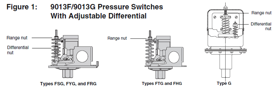
a. Turn the range nut clockwise for higher cut-in pressure, or counterclockwise for lower cut-in pressure. See Figure 1.
NOTE: Adjusting the cut-in setting does not change the differential. As the cut-in value changes, the cut-out value changes by the same amount and in the same direction. For example, increasing the cut-in pressure by 10 psi will also result in an increase in the cut-out pressure by 10 psi.
When lowering the pressure setting, remember that most bladder tank water systems are designed for the bladder pressure to be 2 psi below the cut-in point when there is no water in the tank.
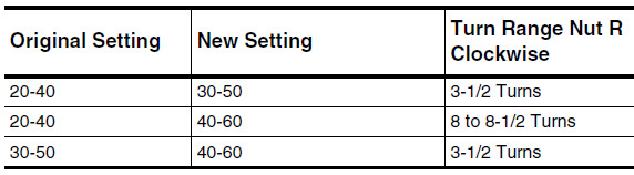
b. Use the table below as a guideline for setting the range nut R. Replace the cover and
restore the power and confirm pump system operation.
5. To increase or decrease the cut-out setting (while maintaining the same cut-in pressure) adjust the pressure switch with a 3/8 inch nut driver or socket as follows:
a. Complete the following 6 steps.
→ Disconnect the power.
→ Remove the cover.
→ Visually inspect the pressure switch for leakage. Verify that: - No liquid is leaking from the diaphragm or flange area. — The flange is not corroded. — The area is free of standing water and wet spots.
→ Check all plumbing connections. Verify that: — The flange is not corroded. — The fittings are secure and without white residue (lime deposits).
→ Check all electrical connections. Verify that: — The wires are not pinched or frayed, and the insulation is not cracked. — There are no insects, contamination, or nests. If found, remove.
NOTE: Contacts may appear pitted. Do not sand or file the contacts. Do not use chemicals to clean the contacts.
→ Check the system pressure using a pressure gauge.
b. Turn differential nut D clockwise for a higher cut-out pressure, or counterclockwise for a lower cut-out pressure. See Figure 1.
NOTE: Adjusting the differential changes the cut-out setting. The cut-in does not change.
c. Complete the following 3 Steps
→ Replace the cover.
→ Restore the power and confirm pump system operation.
→ Open a tap or spigot to confirm water flow.
6. Monitor the system to ensure that the pressure setting is as desired.
a. Open a faucet and drain water from the system until the pump turns on.
b. Turn off the faucet.
c. Monitor the system pressure to identify the point where the pump turns off.
d. Repeat the following 3 steps as required.
→ Check all electrical connections. Verify that: — The wires are not pinched or frayed, and the insulation is not cracked. — There are no insects, contamination, or nests. If found, remove. NOTE: Contacts may appear pitted. Do not sand or file the contacts. Do not use chemicals to clean the contacts.
→ Check the system pressure using a pressure gauge.
→ Replace the cover.
End!
From time to time, we get a call that starts with “I tried to adjust my pressure switch and it is totally messed up, how can I get back to the factory pressure switch settings?"
No need to panic, you are not the first nor will you be the last to have messed up your pressure switch settings so that you cannot get it back to the factory settings or to the cut-in and cut-out setting that you were aiming to achieve. Check out this link for more information:
https://support.boshart.com/i-have-totally-messed-up-my-pressure-switch-settings-now-what