How do I adjust a relief valve?
PRESSURE RELIEF VALVE INFORMATION - IMPORTANT – READ CAREFULLY
Every installation where the pump is capable of producing more pressure than its related system components (e.g. pressure tank) are rated for, must have a pressure relief valve. Accidental sticking of the pressure switch contacts can cause the pump to continuously run developing pressures that could burst the tank.
Not all relief valves are adjustable, ECONOMY relief valves are factory set at either 75 PSI or 100 PSI and they are NON-ADJUSTABLE!

RVHD series pressure relief valves are typically factory set to open at 75 PSIG on 1/2” through 1” valves and the 1-1/4” through 2” valves are set to open at 65 PSIG.

It is the responsibility of the system designer or installer to properly select a pressure relief valve with adequate flow characteristics to maintain a maximum pressure considerably below the system’s design pressure. Usually, this is determined by the maximum pressure rating of the pressure tank. Consult the tank manufacturer for the maximum pressure rating for your tank.
The following flow guide may be used to help select the proper size relief valve for your application. If you are near the maximum GPM, it is recommended to go up a minimum of one size to ensure there is adequate flow to compensate for friction loss in the piping.


Field adjustment is NOT recommended on pressure relief valves. If the factory setting is changed in the field to increase the pre-set opening pressure, the installer MUST test the system to verify the changed setting will still allow adequate pressure relief relative to the capacity of the entire system. For example, the submersible pump’s total head and flow cannot exceed the pressure tank’s rated capacity if the pressure switch fails to cut-off the pump.

Failure to verify could cause serious damage, personal injury, or death.
This test is accomplished by SAFELY bypassing the pressure switch while watching a calibrated pressure gauge in the system. The tester must be in a position to switch off the pump manually if the system pressure approaches the maximum rating of the pressure tank. If the output of the pump exceeds the capacity of the “re-set” pressure relief valve, a higher flow rate PRV must be selected.
RVHD SERIES RELIEF VALVE ADJUSTMENT INSTRUCTIONS
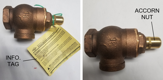
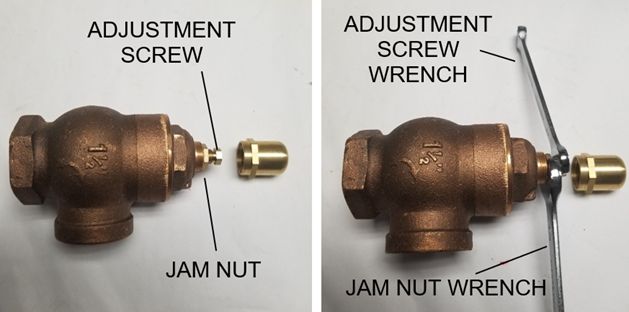
#1 - All adjusting screws are concealed with acorn nuts to prevent tampering. With the pump or compressor running, remove any tags and the acorn nut.

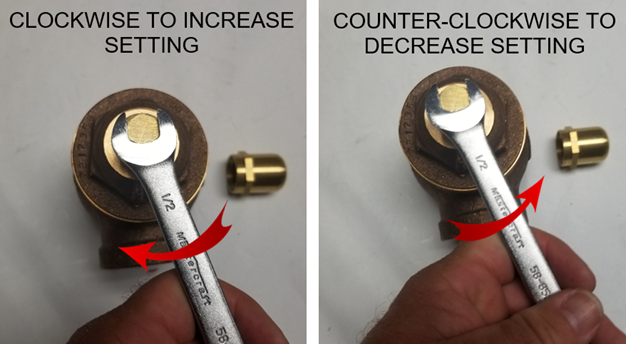
#2 - Loosen the jam nut and reduce the spring tension by turning the adjustment screw counterclockwise until the pressure gauge is below the desired setting.

#3 - Then retighten the adjusting screw tension by turning the adjustment screw clockwise to the new desired setting.

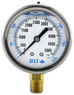
#4 - Test the setting, the gauge needle will drop abruptly at the relief setting. This test is accomplished by SAFELY bypassing the pressure switch while watching a calibrated pressure gauge in the system. CAUTION: The tester must be in a position to switch off the pump manually if the system pressure approaches the maximum rating of the pressure tank. If the output of the pump exceeds the capacity of the “re-set” pressure relief valve, a higher flow rate PRV must be selected.
NOTE: Any system must be capable of producing a higher pressure than desired for accurate setting. Arbitrarily tightening the adjusting screw without a relief drop on the gauge is not recommended.

#5- Replace the acorn nut and recheck the relieving pressure setting.
