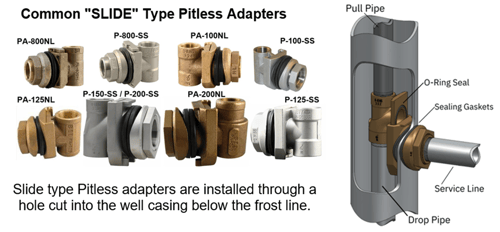
Let us start by clearing up some of the fear of the unknown for those who are new to spool type/industrial pitless'. The bottom line is that they are simple in concept and regardless of the type, slide, weld-on, clamp-on or spool, which are commonly referred to as industrial pitless adapters, they all perform the same basic function. Therefore, one should not let the unique design and different terminology get overwhelming.
 Typically, spool type/industrial pitless adapters are installed on larger municipal water wells with an 8” diameter or larger well casings. This is why they are referred to as “industrial” pitless'. However, they are also available in 5” and 6” models which are often referred to as “residential” spool type pitless'. The terms industrial and residential can cause added confusion. In our opinion, the size of the pitless does not determine what application it is used for. Smaller sizes of pitless units can also be used in industrial applications.
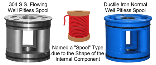
The spool terminology is derived from the shape of the inner component. It is referred to as the spool because it has the shape of a spool of thread or wire. The spool both supports the pump column and redirects the water 90° from the vertical flow up the drop (or riser) pipe and out the discharge to the service line. The watertight seal between the pitless discharge housing and the spool is made by two O-Rings installed in precision machined grooves in the spools upper and lower flange sections.
Industrial spool type pitless'…
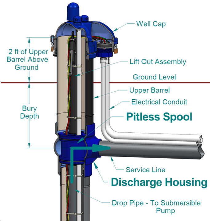
- Are sold as pitless units, meaning they are typically sold with the spool type pitless adapter factory assembled to the upper barrel. This is simply the well casing section above the pitless adapter, the well cap, and the lift out/hold down assembly (see diagram below).
- Can support extremely heavy pump columns making them ideal for deep pump sets and large diameter drop/riser pipe installations. The pump column weight is supported by the thick, heavy duty, bottom portion of the casting with the drop pipe connection.
- Are of “clear-way” design which simply means there is no obstruction or reduced diameter to the well casing passing through the pitless adapter housing.
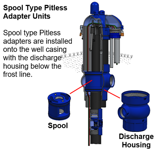
The diagram below illustrates the discharge housing and spool components of the industrial pitless units which create a two-piece 90° elbow to direct the flow of water from the submersible pump into the service line buried below the frost line to prevent freezing. An upper barrel extends the well casing to the surface for easy access to the well and an additional section 2 ft. above ground prevents surface water from contaminating the well.
 Additional Resources:
https://support.boshart.com/how-do-i-properly-install-my-pitless-adapter
https://support.boshart.com/how-do-i-install-a-spool-type-industrial-pitless-unit
https://support.boshart.com/do-the-spool-type-industrial-pitless-adapter-units-have-hold-down-hooks
https://support.boshart.com/how-do-i-install-a-wtcl-c-series-industrial-well-cap
For information on the pitless units see the "Municipal and Industrial Pitless Well Systems Booklet."
For details on the well cap part numbers WTCL-C10 (8” Pitless Units), WTCL-C12 (10” Pitless Units), and WTCL-C14 (12” Pitless Units), refer to the link below (details on pages 74 to 77).