NOTE: PITLESS UNITS ARE TYPICALLY ATTACHED TO THE WELL CASING BY WELDING.
Always refer to and comply with all applicable well construction codes.
Always refer to your State or Provincial local and municipal water well regulations for installation requirements.
To install an Industrial Pitless Unit, an excavation around the well casing below the frost line is made and the well casing is cut off at a prescribed level. The upper barrel is then welded or threaded tightly onto the well casing. The submersible motor, pump, and cable are attached to the drop pipe which is lowered into the well with a hoist.
When the top of the last section of the drop pipe is one foot above the Pitless case, the lift-out / hold-down hook assembly and spool are then threaded onto the drop pipe. The spool assembly and drop pipe with the motor, pump and cable are lowered into place, then the electrical service and well cap are installed.
STEP-1
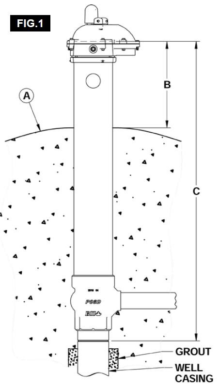
The finished grade (ground level) at the well location must be determined (FIG.1-A). The ground must slope away from Pitless case in all directions.
NOTE: The well casing must be cut off at a distance below the ground level equal to the overall Pitless Unit length (FIG.1-C), less the length of the Pitless Unit upper barrel / Pitless casing which is to extend above the ground (FIG.1-B). BII Pitless Units are supplied with 24” of upper barrel to protrude above ground (meets and exceeds the minimum requirements) to provide greater protection against surface contamination (FIG.1-B).
Flood Plain Warning: If the well is in a location where contamination from flooding is possible the well must be constructed in compliance with all applicable well codes which may include 100-year flood level requirements and specialized well venting systems to prevent surface water from entering the well if the well head were to become submersed.
STEP-2
Excavate around the well casing according to government regulations where well casing is to be cut off (FIG.2-A). Excavate to provide adequate room to work, 24” to 36” deeper than the bury depth or center of discharge connection (FIG.2-B) is suggested. Then remove grout from existing well casing to just below the cut off level (FIG.2).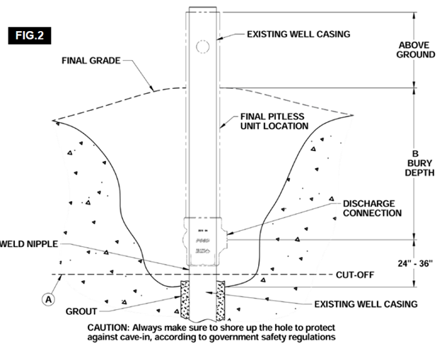
STEP-3
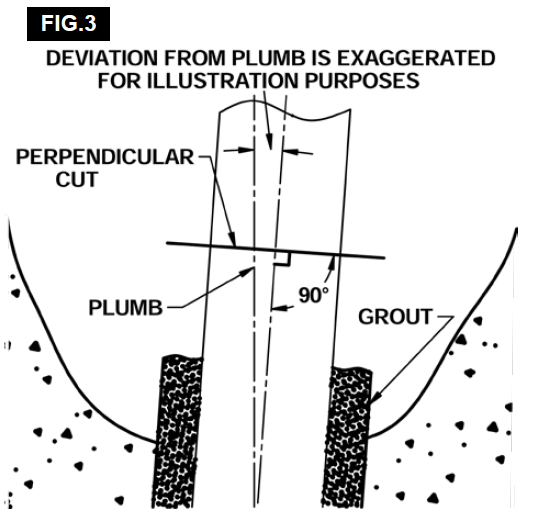
Cut off the well casing perpendicular to the well casing center line (FIG.3). The use of a universal pipe cutter tool equipped with a blade designed to cut large diameter steel pipe / well casing will make a high-quality, straight, square and smooth cut. A rough or uneven cut will make welding more difficult and could reduce the quality of the weld connection.
TIP: If cutting casing with a torch, the use of a cutting torch guide is recommended. Just clamp around the casing, rest the cutting tip on the guide and cut a nice, straight line.
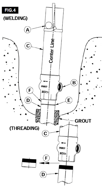
Threading the Pitless Unit to the Well Casing: The beveled weld nipple is loosely installed to allow for easy removal. In the event the well casing is already threaded, simply remove the weld nipple (FIG.4-F) and thread the Pitless Unit (FIG.4-C) directly to the threaded well casing (FIG.4-D).
STEP-4
Using lift straps secured below the hold-down hook pods (FIG.4-A), which double as lifting strap pods to ensure the lifting straps do not slip while Pitless Unit is hoisted into position on the well casing. Rotate the discharge outlet (FIG.4-B) to the desired location for service line. All Pitless Units are designed to be joined either by welding or threading the unit to the well casing.
NOTE: Quick connect / mechanical joint options are available and can be utilized providing they meet the well construction codes for jurisdiction.
IMPORTANT: It is essential that the center line of the Pitless case (FIG.4-C) and well casing be the same (FIG.4-D). Joint between the well casing and the Pitless Unit must be watertight (FIG.4-E).
Welding the Pitless Unit to the Well Casing: All BII Pitless Units are supplied with beveled weld nipple (FIG.4-F) installed (hand tightened only). The nipple must be installed with a high-quality thread sealant and tightened by the installer. The use of an external type pipe joint aligning clamp is recommended to ensure proper well casing to Pitless Unit alignment and to securely hold the Pitless Unit in position while the connection is welded.
STEP-5
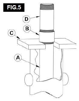
The submersible motor, pump and cable are attached to the drop pipe and then lowered into the well. The top of the last section of the drop pipe (FIG.5-A) will be one foot or more above the Pitless casing (upper barrel). Typically, the last length of pipe has a well coupling installed (FIG.5-B) which is used to support the weight of the pump column using a heavy duty “U” plate (FIG.5-C) or some form of clamping device. A short piece of drop pipe is then threaded into the coupling to connect to the spool / lift out assembly.
TIP: The use of a short section of pipe (FIG.5-D) eliminates issues with the lifting range of the crane or hoist reducing the length of the first section to be lifted (lift pipe and spool assembly) to get to the first drop pipe connection when pulling the pump for servicing or replacement.
STEP-6
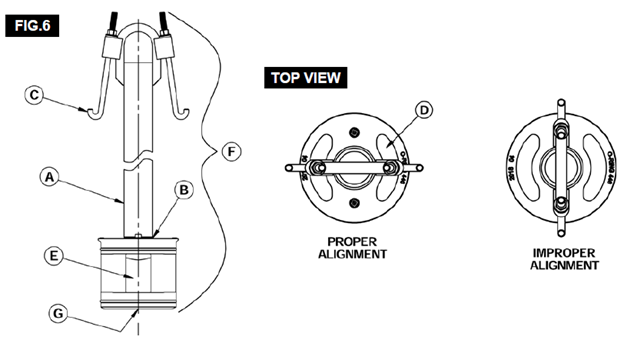
Thread the lift out pipe (FIG.6-A) into the top lift pipe connection of the spool (FIG.6-B). Wrench tighten and make sure to align the hold-down hooks (FIG.6-C) in line with the center of the crescent-shaped through passages (FIG.6-D). This will ensure the water passage (FIG.6-E) will align with the discharge connection for maximum flow when the spool is set, and the hooks are engaged in the hold-down pods on the Pitless casing (FIG.6 top view). Screw the spool assembly onto the drop pipe.
STEP-7
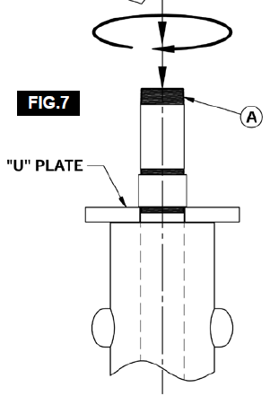
Lower and thread the spool & lift-out assembly (FIG.6-F) into the drop pipe (FIG.7-A pipe column) and then into the bottom drop pipe connection of the spool (FIG.6-G).
STEP-8
With the spool & lift-out assembly securely fastened, the wiring which is attached to the pipe column can now be fed through the passages and secured to the lift out pipe to get the wiring to the well head.
STEP-9
Prior to seating the spool, wipe the rubber O-ring seals and the O-ring seats in the discharge housing with a clean cloth and then coat with a heavy layer of silicone grease which is approved for potable water and food processing applications. Silicone grease is not water soluble and it provides excellent lubrication during installation and aids proper seating of rings.
STEP-10
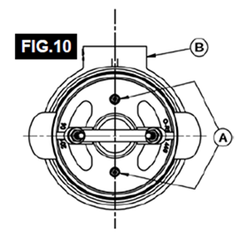
First, verify that the water passage in the spool will align with the discharge outlet in the Pitless housing (if not refer to Step #6).
TIP: Verification is easy. Simply check that the two-pressure zone tapings (FIG.10-A) are in alignment with the discharge outlet (FIG.10-B), with the hooks in alignment with the hold-down pods. Then, slowly lower the pipe column into place. The spool is set when the lower plate of the spool rests against the support ring in the Pitless housing.
STEP-11
Engage the hold-down hooks onto the well casing inside the hold-down hook pods and tighten.
STEP-12
Install lower and middle ring assembly of the well cap following instructions provided with the well cap. Leave the cover off for the time being. Details on page 24 (5” Pitless Unit), page 39 (6” Pitless Unit) and page 74 (8”-12” Pitless Unit).
STEP-13
Complete electrical service.
NOTE: If you have ordered a conduit cable seal, see page 84 or for a conduit splitter follow the installation instructions provided. Details on page 86.
STEP-14
Complete installation of well cap cover (following instructions provided with the well cap). Details on page 24 (5” Pitless Unit), page 39 (6” Pitless Unit) and page 74 (8”-12” Pitless Unit).
STEP-15
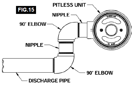
Connect discharge outlet to distribution line.
TIP: You may want to consider the installation of a swing joint (FIG.15) on the discharge which can provide extra protection of the discharge joint / service line against damage due to settling of soil and soil expansion due to frost.
STEP-16
The unit is now ready to operate under power and should be run for enough time to ensure confidence that there are no leaks present at any of the connections.
STEP-17
The excavated hole should not be back filled until the unit is running satisfactory.
STEP-18
Great care must be exercised to compact the fill under the discharge service line during the back-filling process. Always follow all regulations governing the sealing of the bore hole and Pitless / well casing as well as the codes for surface drainage away from the well head. Some areas may simply require a specified surface grade while other jurisdictions may require a cement pad.
STEP-19
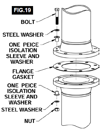
IMPORTANT: Joining dissimilar metals should be avoided.TIP: Solution on "Preventing Galvanic Corrosion" page.