Winterizing a Water Well System Using a Drain Back Valve
The Flomatic Model 70 Automatic Drain Valve automatically opens to the atmosphere when the water system pressure drops below 5 or 10 (PSI). The spring-loaded drain valve operates hydraulically and is designed to close through the water flow velocity in the pipe. The drain valve will provide automatic drainage of pipe water lines in a water system when the line pressure drops below 5 or 10 psi. No adjustments are necessary.


VALVE OPERATION:
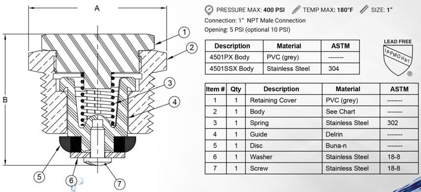
The Model 70 Automatic Drain Valve is normally held open by the force of the compression spring. The Flomatic Valves Auto-Drain Valve Model 70 when properly installed in a water wells riser pipe will drain the piping system when the system pressure is 5 or 10 psi or lower.

NOTE: The Auto-Drain Valve will close automatically when the water flow velocity reaches about 5 GPM or greater in a 1” size pipe.
INSTALLATION:
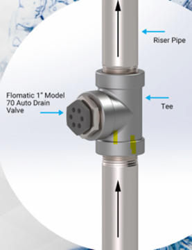
 The Model 70 Automatic Drain Valve should always be installed in an area that would not result in water damage. We recommend installing the valve in a 1” or 1-1/4” water well drop (riser) pipe between the submersible pump and ground level below the frost line. For a 1-1/4” drop pipe you will need a tee pipe fitting which reduces a 1” FPT branch connection.
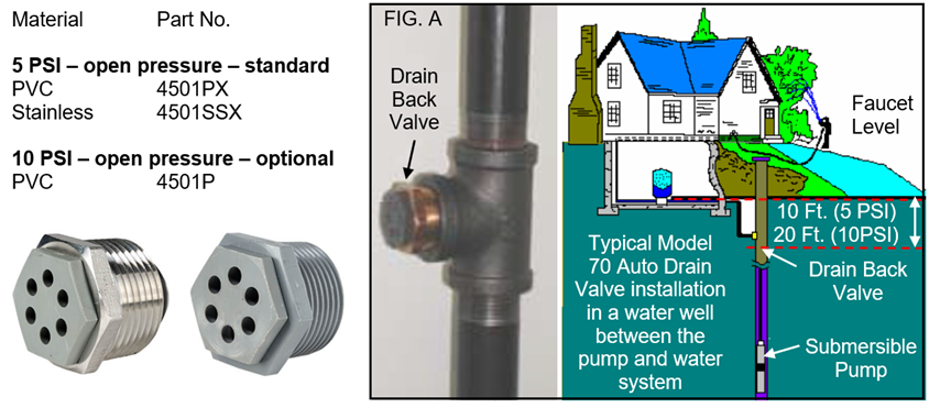
The pipe tee location should be a maximum vertical distance of 10 feet from the closest drain faucet in the water system for valves with a 5 PSI spring, or 20 ft. for valves with a 10 PSI spring.
IMPORTANT: No check valve can be installed between the auto drain valve and the drain faucet as it would prevent water system drain back.
The Model 70 Automatic Drain Valve may be installed in any position, vertical or horizontal. The Model 70 Auto Drain Valve is recommended to be installed in a 1” NPT pipe tee fitting (See Fig “A” for typical installation). The pipe tee shall be located in a 1” or 1 ¼” water well drop pipe between the submersible pump and ground level. The pipe tee’s location shall be a maximum vertical distance of 18 feet from the closest drain faucet in the water system. No check valve can be installed in this pipe section that would prevent water system drain-back.
The Model 70 Auto Drain Valve is not designed for ground burial and should not be installed in a buried valve box or enclosure where damaging from flooding could occur. The Model 70 Auto Drain Valve releases system water at 5 or 10 psi pressure and should always be installed in an area (water drain) that would not result in water damage. Be sure all connections are tight and drip free. No adjustments are required to the valve during or after installation.

Note: Do not install in basement.
Put the enclosed “Flomatic® Valves Auto Drain” sticker on the pump control box to indicate that a Flomatic® Valve Model 70 Auto Drain Valve has been installed in the water well drop pipe. This will help to inform all future service persons who might think that there is a check valve in the well that is not holding or that there might be a pipe leak in the water system.
Note: Check with prevailing government authorities for local installation requirements.
WATER SYSTEM START UP
Be sure that the Model 70 Automatic Drain Valve has been properly installed in the water well. Close all faucets and fixtures and start the submersible pump and allow the system build up its usual system operating pressure. Once the pump reaches its normal shut-off pressure, watch a pressure gauge to ensure water pressure is holding steady. The Model 70 Auto Drain Valve is now re-set in a closed position for normal water system operation.
WATER SYSTEM SHUT DOWN
Shut the power off to the submersible pump. Open the faucet or fixture that is located less than 10 feet in vertical elevation from the Model 70 Auto Drain Valve. The water system pressure is lowered as the faucet is kept open. Once the system pressure reaches approximately 5 or 10 psi, the Model 70 Auto Drain Valve will open and drain the water system back down the well.
https://www.flomatic.com/assets/pdf_files/literature/Auto%20Drain%20lit.pdf
https://www.flomatic.com/valves/check-valves/auto-drain/70-auto-drain/
https://www.flomatic.com/assets/pdf_files/oem/16016.pdf
