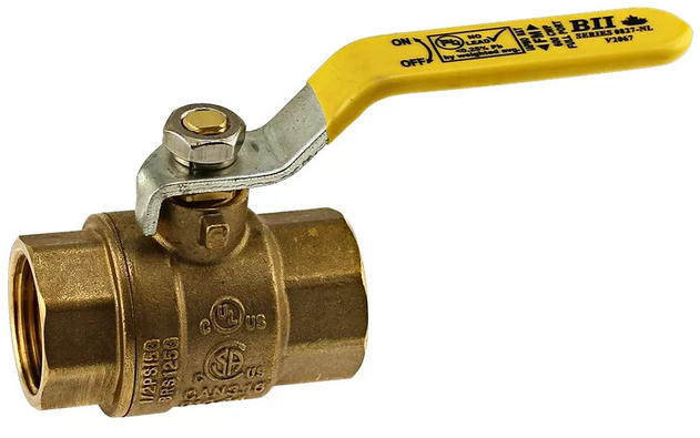
How to Install a Threaded Ball Valve
Threaded ball valves can be installed correctly in just 7 steps. Follow these considerations and steps for an easy and hassle-free installation.
VALVE ORIENTATION:
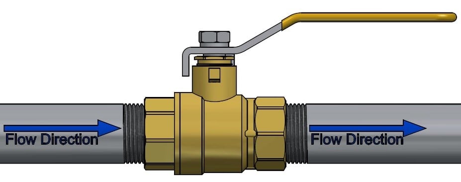
Ball valves may be installed in vertical or horizontal pipe runs. They are bi-directional therefore flow direction is not critical, however the best practice is to set up the valve handle to point in the direction of flow whenever possible. The valve stem orientation is not critical, however any deviation from vertical is a compromise. Installation upside down is not recommended because it can cause dirt to accumulate by the stem packing. The best practice is to install with the valve stem facing upwards whenever possible.
INSTALLATION STEPS
#1 – Inspect the ball valve ports, seating surfaces, and threads to ensure they are clean and free of foreign debris.
#2 – Operate the valve from the fully open to fully closed position.
#3 – Ensure all threaded pipe connections are accurately threaded, clean, and free of foreign material or metal shavings.
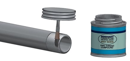
#4 - Apply a high-quality pipe thread sealing compound or PTFE thread sealing tape following the manufacturers application instructions to ensure a leak free pipe joint seal.
#5 – The valve and piping must be in alignment to prevent cross-threading. The male threaded fitting needs to be aligned with the axis of the tapped hole. Maintaining proper pipe alignment during assembly eliminates unnecessary stress on the valve body. Support the valve and piping in alignment to prevent any unnecessary stresses on the valve body by connecting the pipe. Pipe supports must be capable of keeping the pipe in alignment and bearing the weight of the fittings, valves, pipe, and its contents.
WARNING: Failure to properly support piping will void warranty and could result in structural failure and property damage.
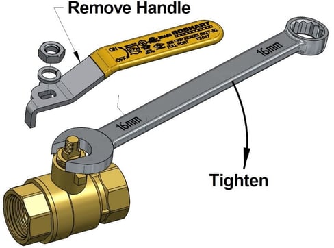
#6 – When installing two-piece body ball valves always use two wrenches when making up pipe joints. Position one wrench on the valve end closest to the pipe joint being tightened and the other wrench onto the pipe to prevent transmitting torque through the valve body joint, between the valve body and tailpiece. This also prevents distortion of the internal parts of the valve.
WARNING: Failure to follow this instruction will stress the body joint and may result in leaking at the body joint.
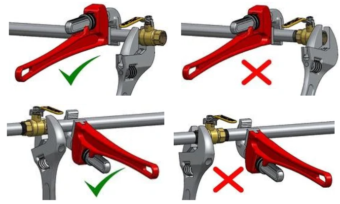
TIP: Brass and bronze alloys are softer metals than steel, always use a smooth-jawed wrench on the valve end and turn the valve onto the pipe. Pipe wrenches should only be used on pipe and fittings.
#7 – Tighten until you can feel the joint starting to seat and the fitting is almost pointing in the desired direction. Then increase the tightening force a little if each attempt gives less movement. Continue to tighten until you have proper alignment, and you should have a sound joint. If the movement stops suddenly, you have probably bottomed out against the stop in the valve body. CAUTION: Never back off a connection to achieve proper alignment.
Loosening valve, pipe and fitting connections will compromise the integrity of the seal and contribute to leakage and failure.
WARNING: Do not over tighten the valve onto the pipe, as it is possible to distort the internal parts of the valve or cause a stress fracture in the valve body. As a general guideline, after hand-tight engagement, tighten an additional 1-½ to 3 full turns for sizes up to 1”. For sizes 1-¼" and larger, 1 to 2-½ full turns should be sufficient. You should have between 3-1/2 and 6 threads engaged. Thread engagement outside of this range may indicate either under or over tightening of the joint or out of tolerance threads.
With experience you will know when the tightening force feels right and you will know when to stop tightening before you damage the fitting or valve.
SYSTEM DESIGN
The required approvals & certifications, pressure & temperature ratings, suitability of the valve component material, valve body, and trim including the seats and seals are solely the responsibility of the system designer. Valves should be installed in piping systems that comply with the applicable portions of the ASME B31 standards. Special considerations may have to be taken with respect to pipeline expansions and contractions and the media expansion and contractions within the piping system.
OPERATION
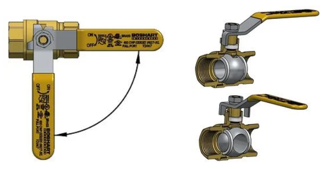
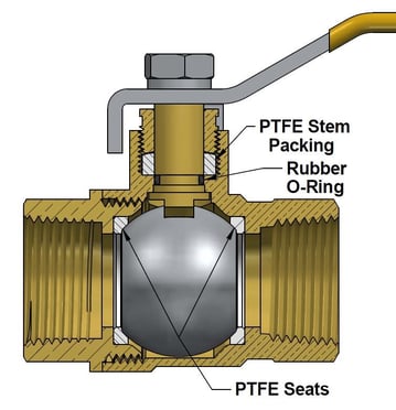
The valve handle is marked showing proper rotation direction for “ON” and “OFF” positions. Rotation is clockwise for “OFF” (closed) and counterclockwise for “ON” (open). You can control the flow by moving the lever between 0° and 90°. A partially open ball valve, however, can leave the P.T.F.E. seats on either end of the ball susceptible to deformity from uneven pressure. One advantage to quarter-turn ball valves is that they can be opened or closed quickly, the disadvantage is that this makes water hammer more likely. For this reason, it’s best to turn the lever on a ball valve slowly.
INSPECTION & MAINTENANCE
#1 - Other than cycling of the valve from the open to closed position periodically, inspection and preventative maintenance are not required.
#2 – Normal stem packing wear can be compensated for by tightening the packing nut. Tighten the packing nut clockwise in 1/8 turn increments until the observed leakage stops.
Over tightening will increase the torque required to operate the valve and result in excessive wear on the packing.
#3 - Do not repack valves under pressure. Repair or replacement of two-piece ball valve's internal parts is not recommended. Damage can occur to the body and tailpiece during disassembly that would make the valve inoperable.