WTCL-C SERIES WATER TIGHT, VERMIN PROOF, LOCKING INDUSTRIAL WELL CAP INTALLATION INSTRUCTIONS
REQUIRED TOOLS: (1) 3/4” wrench, (1) Ratchet with 3/4” Socket & (1) 5/32” Allen Wrench
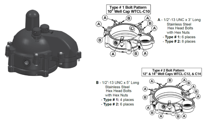
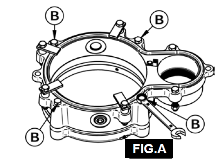
Step 1 - The lower assembly will come out of the box assembled as shown (FIG.A). Using a 3/4” wrench, loosen the B bolts (four places type #1, six places type # 2) which hold the center ring and the lower ring castings together (FIG.A) until there is no compression on the rubber casing gasket seal.
NOTE: Do NOT remove the square nuts. The nuts are recessed into lower ring casting to ensure the well cap is tamper proof. The nuts will not turn when tightening the bolts.
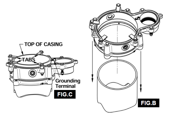
Step 2 - Place lower assembly onto the well casing. (FIG.B) Slide down until the casing contacts the four tabs bolted to the top of the middle ring casting. (FIG.C)
NOTE: Casing should be cut off straight and be free of burrs to ensure a proper fit.
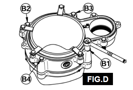
Step 3 - Tighten the B bolts hand tight (four places type # 1, six places type # 2), then tighten an additional two turns in the cross corner type sequence shown (FIG.D) to compress the casing gasket equally between the lower and middle ring to make a watertight seal.
NOTE: The lower well cap assembly will be secure. You should not be able to twist or lift the lower assembly by hand. If the lower assembly can be moved, tighten each bolt one additional turn and repeat until the assembly is tight on the well casing.
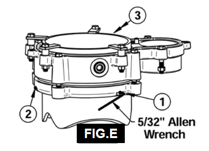
Step 4 - Tighten three grounding set screws in the lower ring (FIG.E) using a 5/32” Allen Wrench.
NOTE: Grounding set screws are only effective in steel well casing applications.
Caution: Grounding requirements may vary depending on state or local electrical codes. Always check and follow your local electrical codes and contact your electrical inspector for details.
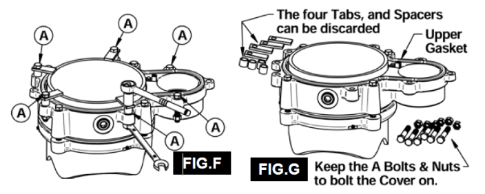
Step 5 - Remove the A bolts and nuts (six places type # 1, eight places type # 2) along with the four sets of tabs and spacers (FIG.F).
NOTE: Keep the A bolts and nuts. They will be needed later to bolt the top cover on. The tabs
and spacers can be discarded (FIG.G).
Step 6 - Make sure that the upper gasket is seated properly in the groove on the top of the middle ring (FIG.G).
Step 7 - Thread the 2” MPT mushroom vent cap, the 2” MPT test cap and the 1-1/2” MPT test cap
(FIG.H) in top cover. Ensure that they are threaded in deep enough to allow installation of the Stainless Steel cotter keys through the holes in the lower portion of the threads (FIG.I). These cotter keys ensure that the vent and caps cannot be removed, maintaining the integrity of the locking / tamper proof design of the well cap.
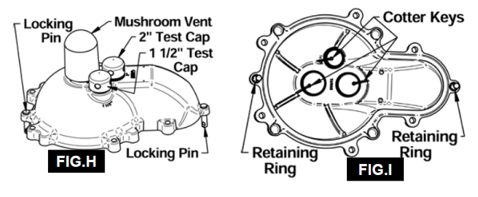
Step 8 - Place the two locking pins through the end holes in the cap (FIG.H) and slide the retaining rings over the locking pins from the bottom (FIG.I). This will keep the locking pins from falling out of the cover when the cover is removed.
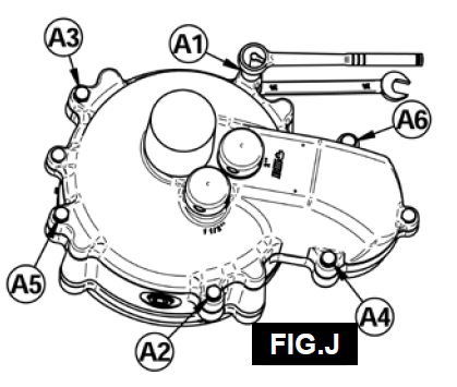
Step 9 - Place top cover on the lower assembly. Make sure that all the holes align and it is completely down over the sealing gasket. The two locking pins should go through the end holes in the middle ring. Place the A Bolts and Nuts through the top cover and middle ring hand tight only (six places type # 1, eight places type # 2). Using the ratchet with a 3/4” socket and a 3/4” wrench tighten all bolts an additional two turns in the cross corner sequence as illustrated in FIG.J, ensuring that the gasket is compressed evenly between the castings all the way around.
DO NOT over tighten.
Step 10 - Insert padlocks through the locking pin holes (FIG.K) at both ends.
NOTE: Padlocks are not included. It is recommended to use 1/4” diameter “U” shank locks.
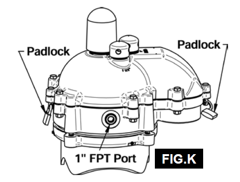
NOTE: There is a 1” FPT Port in the middle ring on both sides that can be used to install additional accessories such as chlorinators or sensor etc