How to Install a Solder Ball Valve
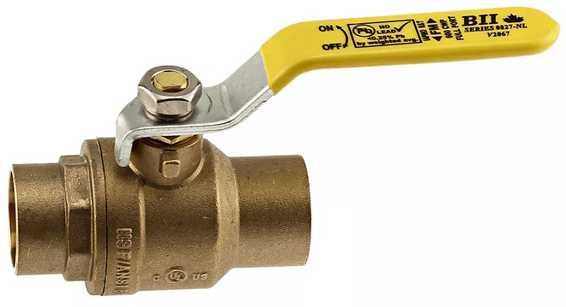
VALVE ORIENTATION:
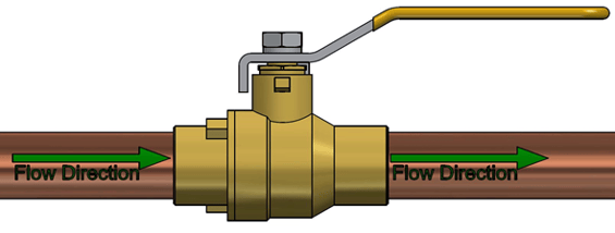
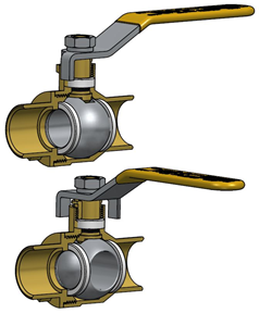
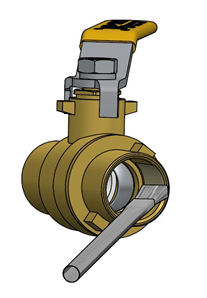
Ball valves can be installed in vertical or horizontal pipe runs. They are bi-directional therefore flow direction is not critical, however the best practice is to set up the valve handle to point in the direction of flow whenever possible. The valve stem orientation is not critical, however any deviation from vertical is a compromise. Installation upside down is not recommended because it can cause dirt to accumulate by the stem packing. The best practice is to install with the valve stem facing upwards whenever possible
INSTALLATION STEPS
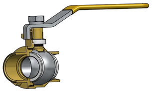
#1 – Inspect the ball valve ports, seating surfaces, and sockets to ensure they are clean and free of foreign debris.
#2 – Operate the valve from fully open to fully closed position.
#3 – Ensure the copper pipe ends being soldered into the valve are square cut, clean, and free of burrs, foreign material, or metal shavings.
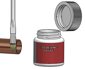
#4 – In preparation for soldering the pipe ends and solder sockets must be thoroughly cleaned with either steel wool or emery cloth.
#5 - Apply a coating of flux paste to the inside of the valve solder sockets and the outside of the pipe ends covering the entire area which is to be soldered.
#6 – Position the valve handle so that the ball is in a partially open position during the soldering process. This is important to avoid the build up of pressure between the valve body and the ball as the heat is applied.
#7 - Support the valve and piping in alignment to prevent any unnecessary stresses on the valve body by connecting the pipe. Pipe supports must be capable of keeping the pipe in alignment and bearing the weight of the fittings, valves, pipe, and its contents.
WARNING: Failure to properly support piping will void warranty and could result in structural failure and property damage.
#8 - Select a torch nozzle that is appropriate to the size of valve being soldered and the fuel gas being used. Always refer to the torch manufacturers recommendations. If you are using MAPP gas or acetylene then you should exercise additional caution as it will be hotter than propane.
Fuel Flame Temperature with Oxygen:
Propane: 5122°F (2828°C)
Propylene: 5245°F (2896°C)
MAPP Gas: 5389°F (2976°C)
Acetylene: 5720°F (3160°C)
#9 - Use no-lead certified, soft solders with melting temperatures of less than 500°F. Many brands of no-lead solders are now available combining low melt temperatures of 410° F with high tensile strength. These solders decrease both the heat and time required to solder the joint.
CAUTION: Valves made from Silicone Brass Alloys require special flux and solders and higher soldering temperatures to make the connection. One should consult with the valve manufacturer for their installation instructions.
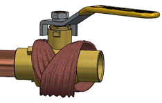
#10 - Extreme care must be used to prevent overheating of the valve causing damage to seats and seals. Wrapping the center portion of the valve in a wet rag will help prevent the center section of the valve from overheating.
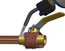
#11 - Start the soldering process by concentrating the heat on the copper tube first, always direct the flame angled away from the valve body joint. After preheating the tube, direct the heat onto the valve solder socket area avoiding the body joint. Move the flame around the circumference of the connection to avoid concentrating the heat on one area which could damage the valves seats and seals.
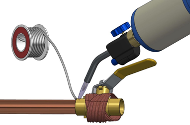
#12 - Touch the solder to the joint and as soon as the solder begins to melt, moderate the heat and continue to apply the solder around the socket the full 360° for vertical installations, the solder will be drawn into the joint and the molten filler metal will cover the entire area to which the flux was applied.
#13 - When the first joint is complete, the valve should be allowed to cool until the valve body is cool to the touch before beginning the second joint. IMPORTANT: Allow to cool naturally, quenching with water will stress the joint / connection unnecessarily.
#14 - After installation is completed, and the valve has cooled, verify the tightness of the packing nut.
SYSTEM DESIGN
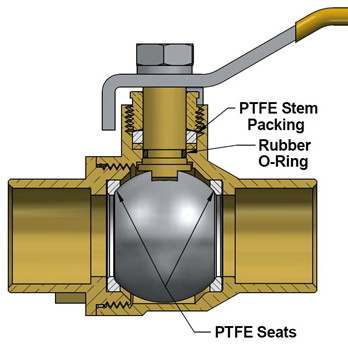
The required approvals & certifications, pressure & temperature ratings, suitability of the valve component material, valve body and trim including the seats and seals (Packing or O-Ring type) are solely the responsibility of the system designer. Valves should be installed in piping systems that comply with the applicable portions of the ASME B31 standards. Special considerations may have to be taken with respect to pipeline expansions and contractions and the media expansion and contractions within the piping system.
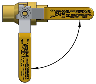
OPERATION
The valve handle is marked showing proper rotation direction for “ON” and “OFF” positions. Rotation is clockwise for “OFF” (closed) and counterclockwise for “ON” (open). The handle indicates the ball port direction. You can control the flow by moving the lever between 0° and 90°. A partially open ball valve, however, can leave the PTFE seats on either end of the ball susceptible to deformity from uneven pressure. Under certain conditions, throttling flow in the near-closed position can destroy the valve seats.
One advantage to quarter-turn ball valves is that they can be opened or closed quickly, the disadvantage is that this makes water hammer more likely. For this reason, it is best to turn the lever on a ball valve slowly.
INSPECTION & MAINTENANCE
#1 - Other than cycling of the valve from open to closed position periodically, inspection and preventative maintenance are not required.
#2 – Normal stem packing wear can be compensated for by tightening the packing nut. Tighten the packing nut clockwise in 1/8 turn increments until observed leakage stops. Over-tightening will increase the torque required to operate the valve and result in excessive wear on the packing.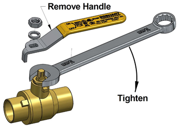
#3 - Do not repack valves under pressure. Repair or replacement of two-piece ball valves internal parts is not recommended. Damage can occur to the body and tailpiece during disassembly that would make the valve inoperable.