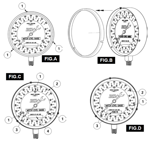
INSTRUCTIONS FOR PG45-WL 4-1/2” WATER LEVEL GAUGE To change the setting of the adjustable dial ring, loosen the three screws on the outside of the gauge (FIG.A-1), and remove the ring and glass from the gauge(FIG.B).
Loosen the three lock screws on the gauge face (FIG.C-1) and rotate the outer disc (FIG.C-2) by pressing your fingers on the surface near the outer edge until the air line length on the dial aligns with the needle (FIG.C-3). The length of the air line should be marked in the block provided on the inner dial (FIG.C-4) to provide a permanent and ever present record of the length of airline (FIG.D). The readings are taken on the inner scale (FIG.D-1) if the air line length is up to 190 ft. Where air line length exceeds 190 ft. the same procedure as outlined above is followed, except that readings are taken on the outer scale of the adjustable dial ring (FIG.D-2).
The example shown (FIG.D-3) is set at 100 ft. of air line.
The adjustable dial ring is set for the length of the air line. Air pressure is then applied
to the air line, purging the air line of water and causing the pointer to move away from
the stop pin in a clockwise direction. When the air line has been completely purged
of water the needle will remain stationary, indicating the water level in feet from the
surface (FIG. E).
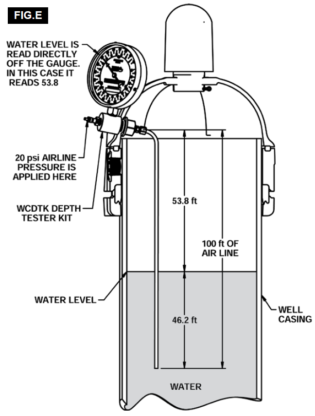
In the example (FIG. E) there is 100 ft. of air line. The air line consists of a small
diameter pipe or tube long enough to extend to a point about 20 ft. below the
lowest anticipated water level. The air line should be hung vertically without any bends
or twists in it, and the exact length should be known. In the example, the bottom end
of the air line is 46.2 ft. below the surface of the water, therefore the water level from
the top of the well = 100 - 46.2 = 53.8 ft. When air is blown through the air line, the
needle in PG45-WL Water Level Gauge will indicate this water level in feet. (53.8 ft. in
this example).