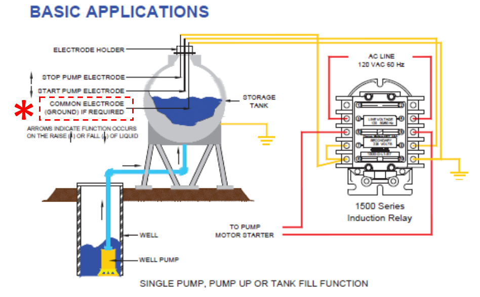
The answer can be two or three depending on the installation. It depends on the grounding circuit. We recommend using a third common electrode for the ground circuit in all installations, the third electrode must extend below the longest operating electrode.
The following is the notation from page 2 of BW Controls 1500 Series Induction Control Relays the installation and Service manual.
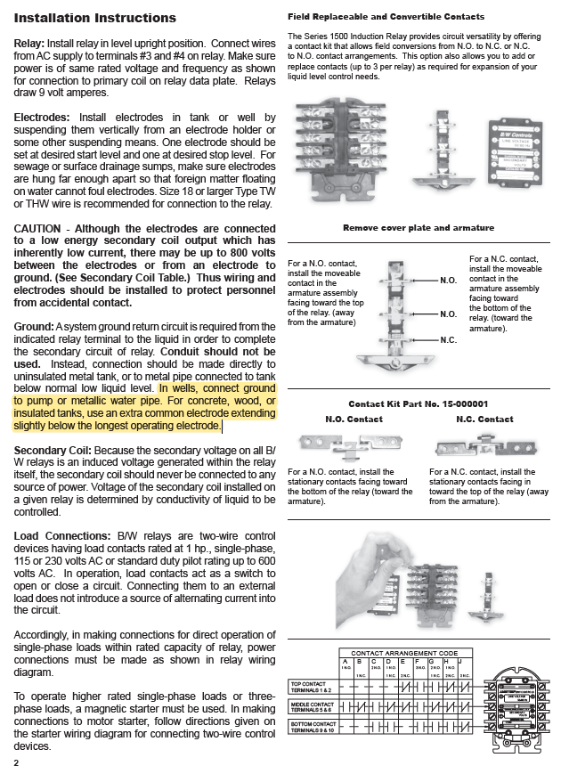
Ground: A system ground return circuit is required from the indicated relay terminal to the liquid in order to complete the secondary circuit of relay. Conduit should not be used. Instead, connection should be made directly to uninsulated metal tank, or to metal pipe connected to tank below normal low liquid level.
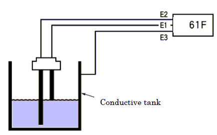 In wells, connect ground to pump or metallic water pipe. For concrete, wood, or insulated tanks, use an extra common electrode extending slightly below the longest operating electrode
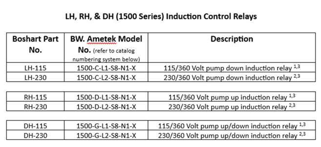
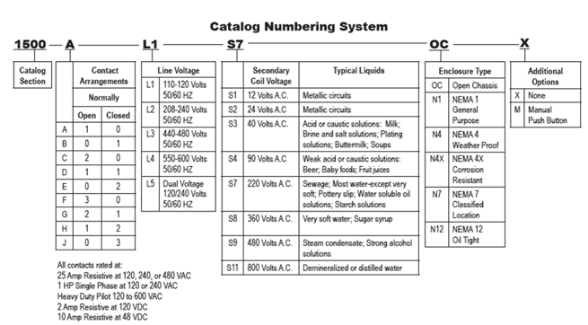
- 115 V is the supply line voltage (L1). This covers line voltages of 110, 115, and 120V (i.e. your relay can be supplied with line voltages from 110-120 VAC). Supply line voltage is the power going to the electrical system.
- 230 V is the supply line voltage (L2). This covers line voltages of 220, 230, and 240 V (i.e. your relay can be supplied with line voltages from 220-240 VAC). Supply line voltage is the power going to the electrical system.
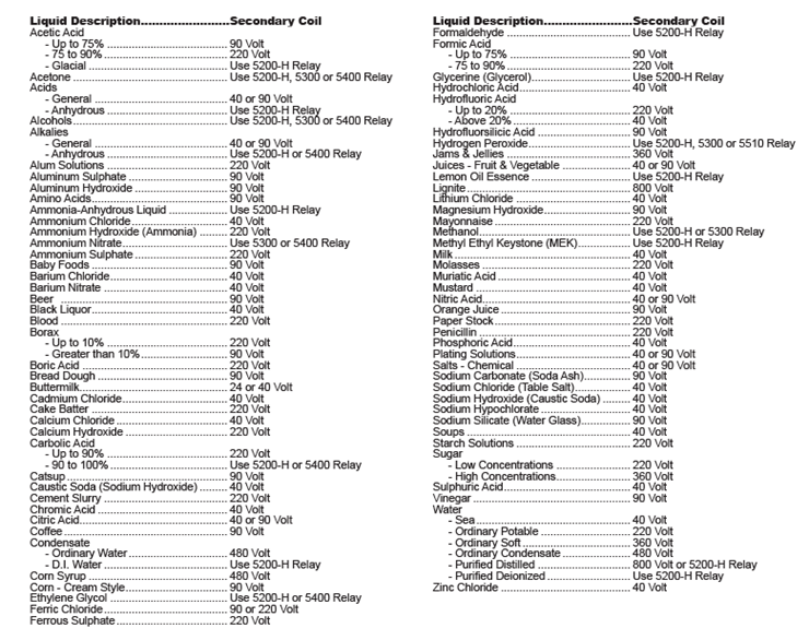
- 360 V is the secondary coil voltage (S8). Secondary coil voltage is chosen based on the conductive liquid in your system. The secondary coil voltage is chosen so that the resistance in the secondary coil is greater than the resistance in the conductive liquid. 360 V can be used for ordinary, soft water and highly concentrated sugar, for example. Refer to the chart below.
Page 2 of BW Controls 1500 Series Induction Control Relays the installation and Service manual.
Additional Resources:
How do I install a BW 1500 series induction relay? (boshart.com)