Following the installation tips below can greatly reduce the risk of property damage due to a component in your sump pump system failing. How long sump pumps, check valves, and other components will last is almost impossible to answer. It’s much like asking how long your fridge, your lawn mower, or your car will last. It simply depends too much on how often the pump has to run. If you have a small sump basin (pit), and you have a lot of ground water in your area, the pump may have to run several times per hour. Naturally, that pump is not going to last as long as the same pump in the home of someone with a large sump pit and very little ground water where the pump only has to run a few times a month or even a year.
Choosing a pump, check valve, and piping that is properly sized to your ground water conditions, along with an appropriate float switch for your sump pit which has a good reliable electrical supply will ensure the longest possible life for your sump pump system. It is not a matter of if, but rather when, one of the critical components will fail. Therefore, the proper precautions must be considered when designing a system to ensure that an adequate back up system is in place. In addition, the system must be regularly checked to ensure all components are working properly.
Having a backup or secondary pump is like having insurance on your car or home. It’s only needed when it’s NEEDED. A backup pump can be standing by and operate when your main pump cannot. This may be because of a power outage, an extreme amount of incoming water, or even main pump failure. Having a second AC-powered sump pump in the pit can protect you in case the main pump simply can’t keep up, or if the main pump fails, but it cannot help you if the power goes out.
TIPS...
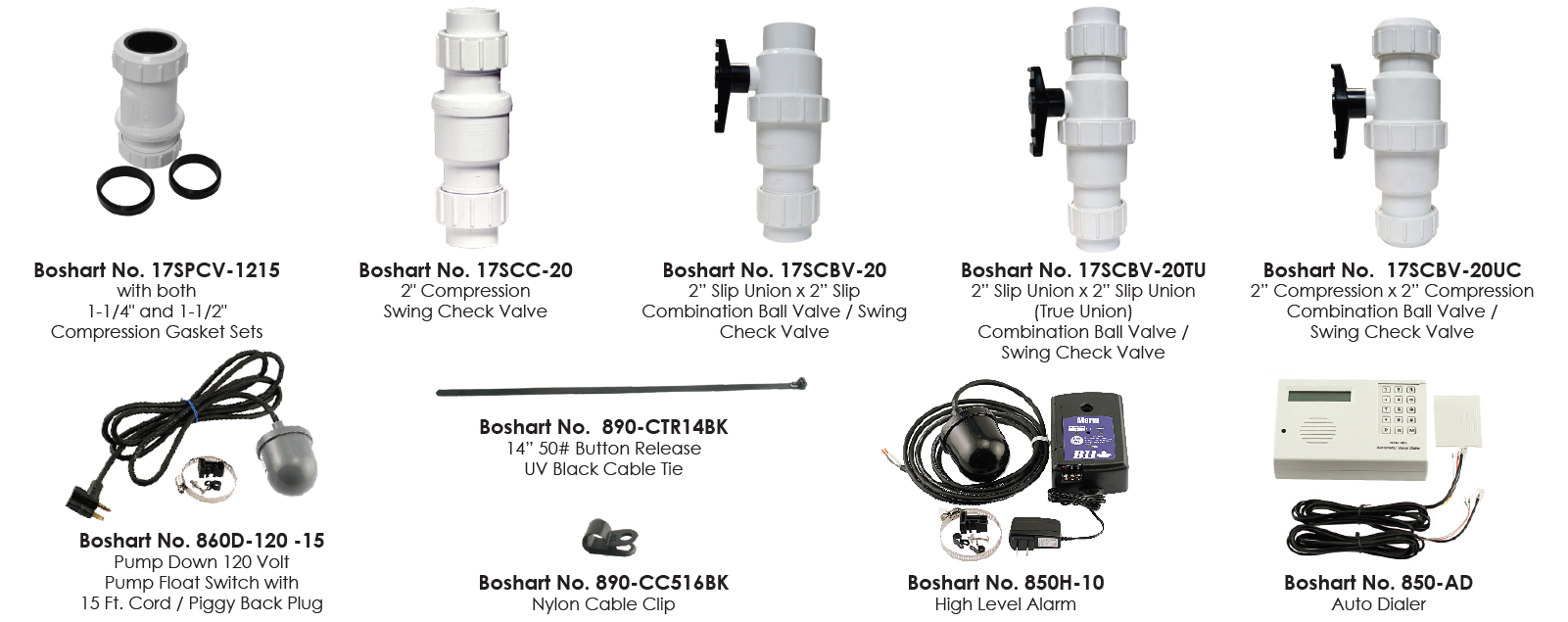
When using compression type check valves such as the series 17SPCV or 17SCC swing check valves or the series 17SCBV combination ball and check valves, “End Blocking” or “Thrust Blocking” is required to firmly secure the discharge pipe! When done properly the risk of joint separation (pipe blow-out) due to hydraulic shock is completely eliminated (see #7 & 16).
Each electrical component of a sump pump system MUST be wired directly to a dedicated circuit to prevent catastrophic system failure if one circuit were to fail.
The installation of a sump pump air gap device a.k.a. an ice guard device in each discharge line outside of the house wall is highly recommended in all systems. This will prevent backups caused by a blockage of the discharge pipe by foreign debris or in regions where drainage lines could potentially freeze. The air gap allows the water to escape onto the ground surface allowing the sump pump to continue normal operation.
Outdoor drain piping should discharge water past the back-fill zone, at least 10 feet from the foundation wall. CAUTION: Codes may vary - Always make sure the sump pump discharge is in compliance with local plumbing codes and regulations!
A high level alarm, connected to an auto dialer is a great investment. I will advise of a pending system failure when no one is home (be assured failure will occur at the most unexpected time). Getting alerted wherever you are allows for corrective actions to be taken before serious property damage occurs.
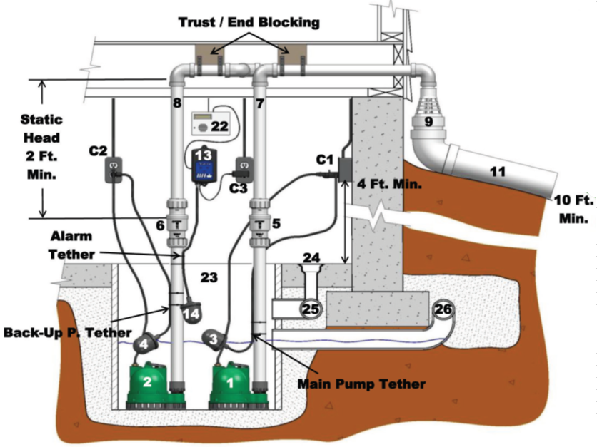
#1 - Main sump pump (120VAC or 240VAC electric).
#2 - Backup sump pump (120VAC or 240VAC electric) connected to automatic standee generator in case of power failure or an additional 12V battery backup system wherever pump failure could result in property damage.
#3 - Main pump float switch with piggy back plug (Boshart Series No. 860D / 862D).
NOTE: Sump pumps must be powered by a dedicated power circuit (See “C1”).
#4 - Backup pump float switch with piggy back plug (Boshart Series No. 860D / 862D). NOTE: This switch is typically installed at a slightly higher “pump-on” level and will provide added pumping capacity in the event the main pump cannot handle the incoming water volume, will provide back up in the event the main pump fails, or provide backup if the "C1" breaker trips (fuse blows). The back up pump must also be powered by a dedicated power circuit “C2”.
TETHER POINTS: The tether points can easily be made and adjusted using a cable tie (Boshart No. 890-CTR14BK). Refer to the float switch tether length chart for desired pumping range.
DEDICATED POWER CIRCUITS: Dedicated power circuits from the breaker panel for each component are helpful in preventing catastrophic system failure.
NOTE: Building codes will require a ground fault circuit interruption (GFCI) outlet at a minimum of 4 feet from the floor on a dedicated circuit as the power source for a sump pump.
SECURE PLUG: The piggy back plugs must be secured to ensure they do not accidently come disconnected from the outlet. Secure the plug and cord with Boshart No. 890-CC516BK nylon cable clips.
#5 & #6 - Swing check valves (Boshart Series No. 17SPCV / 17SCC / 17SCTU). NOTE: Swing check valves perform best when installed in the vertical position. In the event the valve must be installed horizontally, it is critical to install the valve in the proper orientation as marked on the valve body to ensure the flapper operates properly.
NOTE: A minimum of 2 feet of static head above the valve is required. The installation of the check valve just above the sump basin cover (within 1-2 ft.) will provide 5-7 feet of head depending on the height to discharge to the outside. This is ideal for swing check valve operation.
#7 & #8 - Discharge Piping (from main & back up sump pumps) - When using compression type check valves such as the series 17SPCV or 17SCC swing check valves or the series 17SCBV combination ball and check valves, “End Blocking” or “Thrust Blocking” must be installed to firmly secure the discharge pipe. When done properly the risk of joint separation (pipe blow-out) due to hydraulic shock is completely eliminated. Never join discharge pipes into one single discharge pipe through the wall to the outside.
#9 & #10 - Ice guards for main and back up discharge pipes. NOTE: An “Ice Guard System” is a fitting that attaches to the top of your discharge pipe on the outside of your home. One is required for each sump pump installed in your home. Slotted openings along the outer facing side of the fitting provides an alternative (second way) for the water to escape out in the event the discharge pipe becomes clogged with ice or debris.
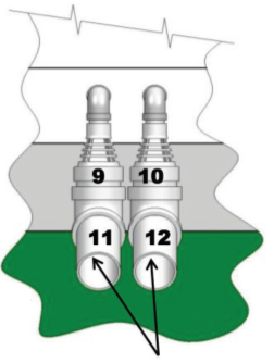
#11 & #12 - Outdoor discharge pipes for the main & backup sump pump discharge pipes should discharge water past the back - fill zone, at least 10 feet from foundation wall.
#13 - High level alarm with 9-volt battery backup (Boshart Series No. 850H-XX C3). The alarm must be on a dedicated circuit from the breaker panel “C3”.
NOTE: Building codes will require a ground fault circuit interruption (GFCI) outlet at a minimum of 4 feet from the floor on a dedicated circuit as the power source for an alarm system.
#14 - Control float switch for high level alarm (included with 850H series alarm).
#22 - Auto dialer (Boshart No. 850-AD).
#23 - Sump pump basin (pit). NOTE: Depending on the size of the sump basin there may not
be enough room for multiple float switches without the risk of entanglement. The alarm circuit can be equipped with a probe type water sensor (Boshart No. 850-WSP) for basin high water detection.
#24 - Floor drain.
#25 - Interior drain tile at perimeter.
#26 - Weeping tile.